
Czujnik prędkości Matek ASPD-DLVR
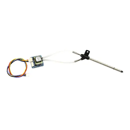
Cyfrowy Czujnik prędkości Matek ASPD-DLVR – Precyzyjny pomiar prędkości dla UAV
Obecnie najlepiej obsługiwane czujniki prędkości przez ArduPilot.
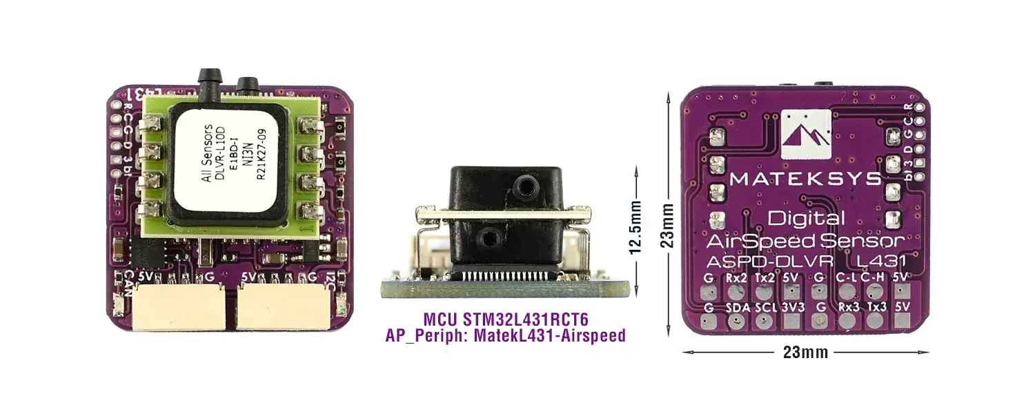
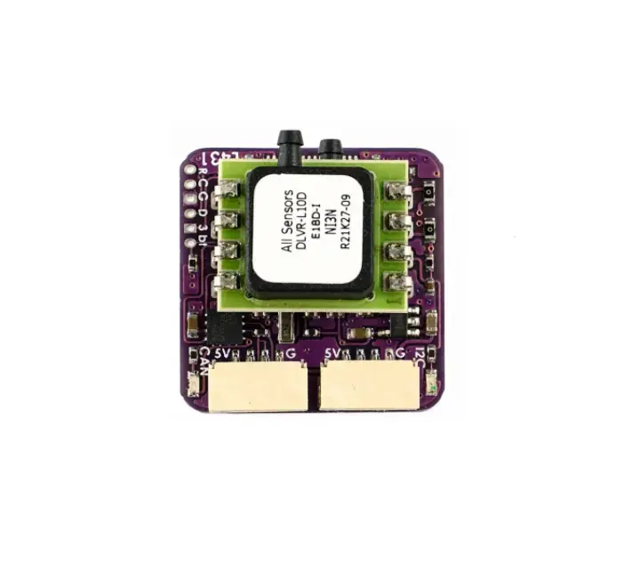
Ze względu na niedobór STM32F405RGT6, ASPD-DLVR został zaktualizowany o węzeł CAN L431 od marca 2022 roku. Wersja L431 ma identyczny rozmiar PCB (fioletowa płytka) i układ jak poprzednia wersja F405.
Najważniejsze cechy Czujnika prędkości Matek ASPD-DLVR
- Węzeł CAN ArduPilot AP_Periph L431,
- DLVR-L10D firmy All Sensors, zakres temperatur przemysłowych,
- Interfejs CAN i I2C,
- Typowe platformy: Fixed-Wing, QuadPlane, VTOL,
- Złącze CAN JST-GH, protokół UAVCAN,
- Złącze I2C JST-GH, DLVR-L10D tryb I2C (adres I2C 0x28),
- UART2: aktualizacja oprogramowania,
- UART3: zapasowy do zewnętrznego GPS,
- UART3: protokół MSP (do obsługiwania),
- Dioda LED zasilania 3,3 V, czerwona,
- CAN bootloader LED (blue)
- Szybkie mruganie: Brak komunikacji między węzłem CAN a kontrolerami lotu (bootloader AP_Periph mode),
- Powolne mruganie: Nawiązana komunikacja między węzłem CAN a kontrolerami lotu
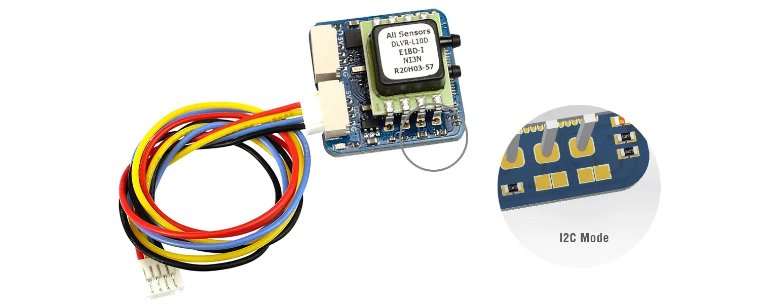
Digital AirSpeed Sensor ASPD-DLVR Specyfikacja
Zakres napięcia wejściowego | 4,5 ~ 5,5 V |
Pobór prądu | 60 mA |
Temperatura pracy | od -20°C do 85°C |
Zakres ciśnienia | 2500 Pa (± 10 w H2O) |
Ciśnienie maksymalne | 75 kPa |
Zakres prędkości | ±250 km/h |
| Wymiary | 23 mm x 23 mm x 12,5 mm (version F405) |
Waga | 4 g |
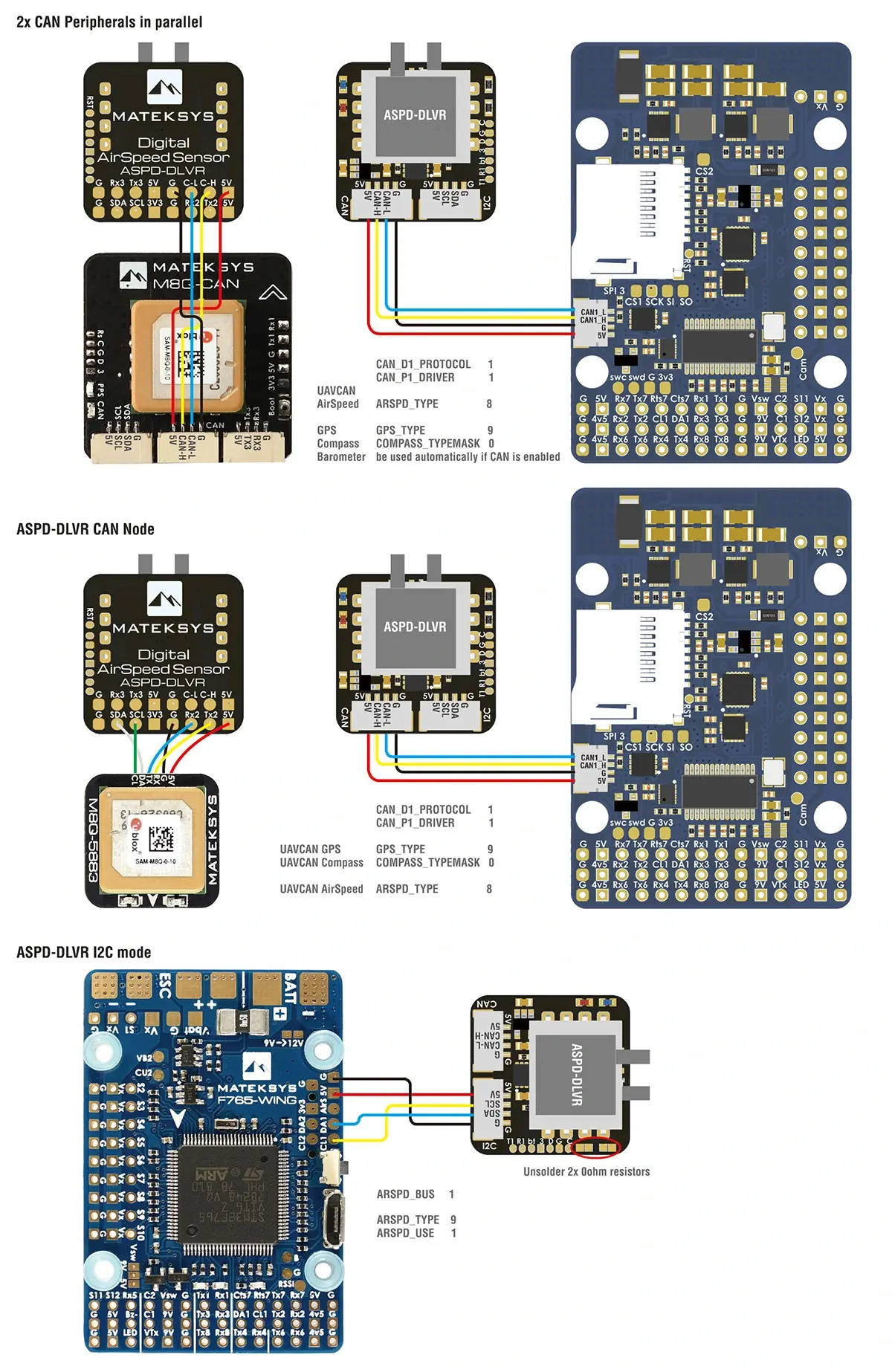
Okablowanie i parametry AP
Połączenie CAN
ASPD-DLVR | Kontroler lotu |
5 V | 5 V |
C-H | CAN High |
C-L | CAN Low |
G | GND |
CAN_D1_PROTOCOL | 1 |
CAN_P1_DRIVER | 1 |
ARSPD_TYPE | 8 (UAVCAN) |
ARSPD_USE | 1 |
Mission Planner-> Initial Setup-> Optional Hardware-> UAVCAN-> SLCan Mode CAN1 -> Parameters -> ARSP_TYPE | 9 (DLVR-10in) Write and reboot |
Połączenie I2C
ASPD-DLVR | Kontroler lotu |
5 V | 5 V |
SCL | SCL |
SDA | SDA |
G | GND |
ARSPD_PIN | 65 |
ARSPD_TYPE | 9 (I2C-DLVR-10in) |
ARSPD_USE | 1 |
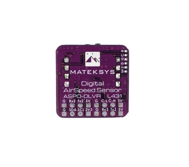
Rozkład pinout i pola lutownicze
CAN
GH-4P Pin | Sygnał | Kolor przewodu |
5 V | input 4~6 V | red |
C-H | CAN high | yellow |
C-L | CAN low | blue |
G | GND | black |
I2C
GH-4P Pin | Sygnał | Kolor przewodu |
5 V | input 4.5~5.5 V | red |
SCL | I2C-SCL | yellow |
SDA | I2C-SDA | blue |
G | GND | black |
Dedykowane pola lutownicze
Pole | Sygnał | Pole | Sygnał |
T1 | UART1-TX | Rx4 | UART4-RX |
R1 | UART1-RX | Tx5 | UART5-TX |
Tx1 | UART1-TX | Rx5 | UART5-RX |
Rx1 | UART1-RX | bt | pin Boot |
Tx2 | UART2-TX | 3v3 | wbudowane wejście LDO |
Rx2 | UART2-RX | D | SWDIO |
Tx3 | UART3-TX | G | GND |
Rx3 | UART3-RX | C | SWCLK |
Tx4 | UART4-TX | RST | NRST |
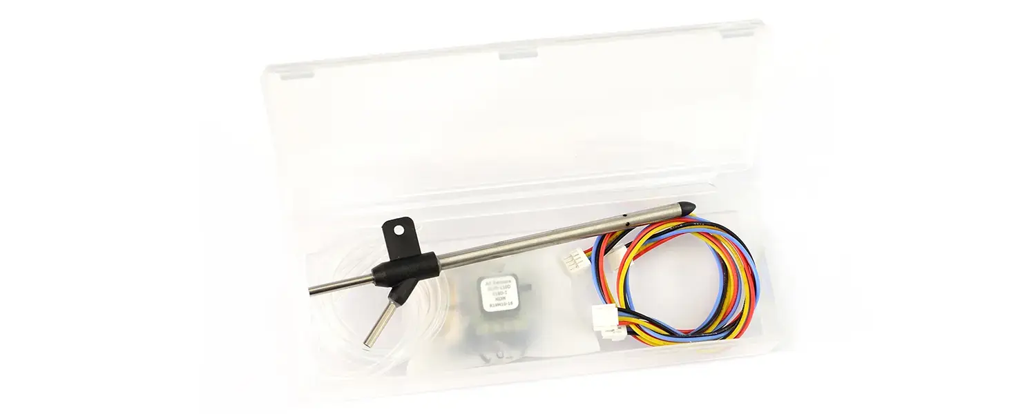
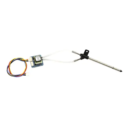
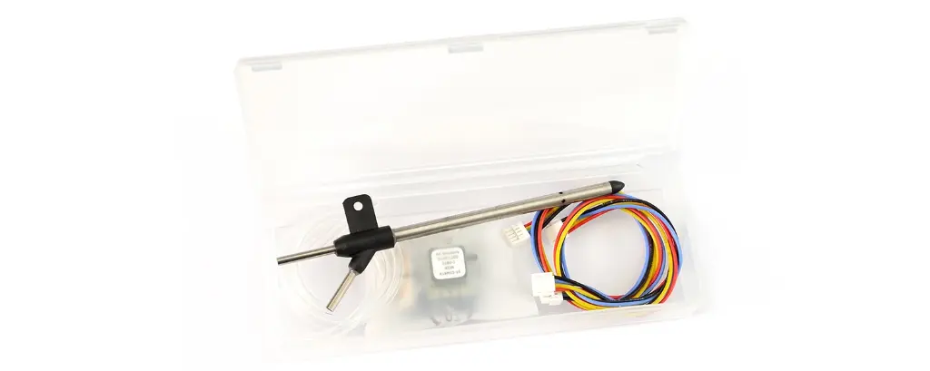
Zestaw Digital AirSpeed Sensor ASPD-DLVR zawiera
- 1x Cyfrowy czujnik prędkości ASPD-DLVR
- 2x 4-pinowe kable JST-GH do JST-GH w silikonowej izolacji (20 cm każdy)
- 1x Rurka Pitota
- 1x Przezroczysta rurka silikonowa 40 cm
TCXO Keeps Frequency Operation Stable
A built-in temperature-compensated crystal oscillator helps the receiver maintain accurate and stable frequency operation as conditions change. For an RC receiver working inside a drone or aircraft, this provides a more controlled frequency reference instead of relying on a basic uncompensated oscillator.
Two Antennas for Greater Link Stability
BR3 uses two high-sensitivity T antennas rather than a single antenna. RadioMaster states that the dual 915/868MHz T-antenna arrangement improves signal stability and range. Both antennas connect independently to the receiver through IPEX1 connectors, giving the BR3 a clear advantage in installations where maintaining a strong RF link is a priority.
Designed to Handle Vibration
RadioMaster uses 0402 components in the BR3 and specifically highlights improved vibration resistance as a benefit of this construction. This is particularly relevant in drones and fixed-wing models, where motors and propellers continuously introduce mechanical vibration into the airframe and onboard electronics.
High Performance Without a Bulky Receiver
Despite its dual-antenna design and telemetry output of up to 500 mW, the BR3 receiver itself measures only 24 mm x 14.2 mm according to RadioMaster's official specification. Its compact footprint makes it easier to integrate into an electronics bay without taking unnecessary space away from the flight controller, video system or other onboard equipment.
RadioMaster Bandit BR3 ExpressLRS 915MHz Receiver Applications
RadioMaster Bandit BR3 ExpressLRS 915MHz Receiver is intended for drones, FPV builds, fixed-wing aircraft and other RC platforms using ExpressLRS and CRSF communication. Its dual antennas, adjustable telemetry output and low-latency architecture make it particularly useful in builds where stable communication and responsive control are important.
The supplied retailer sources also position the BR3 for FPV freestyle and Long Range configurations. Actual operating range depends on the complete radio system, antennas, installation, environment and operating conditions rather than the receiver alone.
Z-Folding Process
By implementing the proprietary Z-Folding process, the BetaFPV LAVA II 280mAh 1S 95C LiHV Battery achieves a 5% higher energy density compared to traditional wound-cell designs. This precision engineering not only enhances the power-to-weight ratio but also significantly extends the cycle life of the BetaFPV LAVA II 280mAh 1S 95C LiHV Battery, ensuring long-term reliability for demanding pilots.
RadioMaster Bandit BR3 ExpressLRS 915MHz Receiver Important Information Before Purchase
RadioMaster Bandit BR3 ExpressLRS 915MHz Receiver is specified by the manufacturer for the FCC915 regulatory domain. Before use, make sure that the selected operating frequency and transmitter configuration comply with the radio regulations applicable in the country where the system will be operated.
The receiver communicates through CRSF rather than conventional individual PWM servo outputs. The connected flight controller or other device must therefore support the appropriate serial interface. RadioMaster specifies a working voltage of DC 4.5–8.4 V.
RadioMaster Bandit BR3 ExpressLRS 915MHz Receiver Dimensions


